Tag Archives: Theater hacking

Building a simple “drop box”

If you’ve ever had a need to drop something onto a stage, be it snow, confetti, a prop brick or rock, or something else altogether, then you’ve likely wanted something called a “drop box”.  As the name implies, it’s a box (or other container) that is used to remotely drop something onto the stage.  While not necessarily suited for snow (unless you want a comedic effect of a bunch of snow all falling at once), it can be useful for dropping many other items.  Building one of these is actually very simple, easy, and best of all inexpensive.

The key to remotely triggering something to drop, unwind, etc. is to have a way to essentially pull a pin electronically.  A common approach to doing this is by the use of solenoids, but solenoids come in all shapes and sizes, and unless you know exactly what you need it can be a daunting task to get the correct one without wasting time & money.  A less expensive approach, which can work just as well, is to use a car door lock actuator.  This is the device that locks and unlocks a car door that has electric locks, and you can find them easily and they’re very inexpensive.  You can find them for sale on sites like Amazon.com for as little as $5.00 each. You can also find them at many car part stores, and if you have access to an automotive junkyard you might be able to get some there for free or very cheaply.

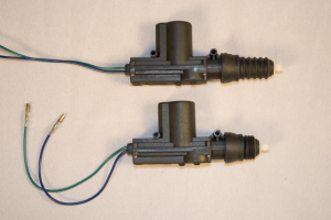
A car door actuator is designed to run on 12 volts DC, however for your needs a regular 9 volt battery is likely enough.  When voltage is applied one way the actuator quickly extends to a fully open position.  When voltage is applied the other way it quickly contracts to a fully closed position.  The distance it travels is approximately 3/4″.  Below is a photo of actuators in fully open and fully closed positions:

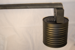
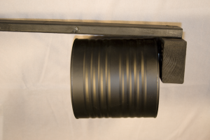
To build a simple drop box you just need a couple pieces of wood, a tin can, a hinge, and an actuator.  Attach a hinge to the back of a tin can and mount it on a block of wood.  Attach the block of wood to a long strap of wood so you have something that looks like this:

The left image shows the can in the “up” position.  It will be held that way by the actuator.  Gravity will then drop it into the position shown on the right, dropping the contents of the can out onto the stage floor.  The wooden block that the hinge is attached to also serves to stop the can from swaying back and forth, but instead keeps it vertical.

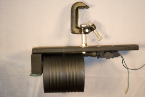
Put the tin can in the “up” position, then mount an actuator on the horizontal strap of wood so that it just holds the can when fully extended.  Make sure that you mount the actuator so that the can drops free when the actuator is retracted.  You might also want to staple a scratch piece of cloth to the bottom of the wooden block that the hinge is on.  This will help to muffle the sound the can makes when it drops.  Add a clamp so you can hang this from a lighting grid and you’re all set:

The one thing I have not done yet is to add a safety cable.  I strongly recommend that you attach a short flexible cable between the clamp or wood strap to the tin can, and I will be doing that shortly after I post this. And as with anything you hang over a stage or audience make sure the whole thing has a safety cable attached to the lighting grid.

All that’s left after this is to wire it up for use.  As mentioned before, a simple 9 volt battery should suffice.  However if you want to get fancy then just wire a DC transformer to it and you can control it from a standard theater lighting system.

Obviously the actuators can be used for all sorts of things. If you need to drop a bunch of balloons, confetti, etc. then just build a larger box with a hinged bottom and use one or more actuators in the same way to hold the bottom closed.  If you need a flag to unfurl just wind the flag around a wooden dowel like it was a window shade and attach a similar dowel along the bottom edge to give it some weight.  Hold the bottom dowel in place with the actuator, and when released the weight of the dowel will unroll the flag.  The possibilities are limited only by your own creativity with making use of the actuators.

Here is a brief video that demonstrates my drop box in action:

Controlling PC/Mac software from a DMX console

I seem to be working on more and more shows where video is used, usually controlled via something like a PowerPoint or Keynote presentation running on a Mac or PC.  Being able to control that remotely via a lighting console would be useful for a number of reasons.  Not only does it let you synchronize things more closely, but it makes it easier for a stage manager to call a show, and also easier for a running crew since they don’t have to worry about whether the next cue means pressing something on the lighting console, something on a keyboard or laptop, or both.

You can find commercial products available that let you simulate pressing a key on a PC/Mac keyboard via DMX, such as Rosco’s KEYSTROKE™, but unless you need to trigger lots of fancy key sequences then the approx. $400 US price tag may be a little much for you.  If all you want is an inexpensive way of pressing a button like the space bar via DMX then there are much more inexpensive ways if you don’t mind a little tinkering.

You basically need two components.  First, you need a DMX decoder that lets you toggle a switch or relay.  The only other thing you need is a module that lets you simulate pressing a key on a USB keyboard.  There are numerous ways of doing both, and depending on how much you’re willing to spend and how much you’re willing to tinker you can spend as little as $0 on a solution.  $80 or so may be more likely, but even that is a much better price to pay than the commercial products!

The DMX interface

If you have an old DMX device lying around you may be able to cannibalize it for its DMX decoder circuit.  If not then you can buy a one channel DMX relay for as little as $40 from places like ApogeeKits or All Spectrum Electronics. For a bit more you can get 4 or 8 channel DMX relays from places like Northlight Systems or Blue Point Engineering. Depending on how fancy you want to get a single channel relay is likely enough for most needs.  Do you only ever plan to control something like PowerPoint or Keynote?  If so then you only need to remotely trigger a single keystroke.  If you need more then how many individual keystrokes do you need?  So 1 may be enough for most cases, but 2, 4, or even 8 may provide you with additional flexibility.

The Keyboard interface

If you have an old keyboard lying around then you already have all the remaining parts you need.  With very little effort you can find many websites that discuss keyboard hacking, or taking apart a keyboard to make use of the guts so that you can make other devices send keystrokes to a PC.

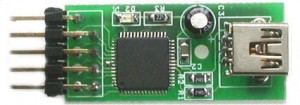
If you don’t have an old keyboard lying around or don’t feel like cracking one open to cannibalize it then you can always buy a USB keyboard encoder, which is basically a device that emulates a keyboard.  This is the approach I chose for a few different reasons.  After hunting around for a while I came across the U-HID Nano, which at $35 fit both my budget and my needs perfectly.  This tiny module (only about 1.5″ long) is fully programmable via a Windows app and lets you specify up to 8 individual keys to emulate.

The U-HID Nano

Things to be Aware of

Depending on what components you scrounge/hack/buy there are various issues you should be aware of.  If you hack a keyboard to use as the PC interface then make sure you’re fully aware of how the keyboard behaves.  By default, Windows, OS-X, linux, etc. all treat a prolonged key press as a signal to repeat that key over and over until you let go of the key.  So if your DMX console sends a prolonged signal to your DMX relay you may find that it results in the computer you’re trying to control interpreting it as multiple key presses.  If you are trying to control an application like PowerPoint this way then you could find yourself cycling rapidly through slides when you don’t mean to.  You might be able to deal with this by doing some rather precise timing work with your lighting console or going into your PC’s settings to reduce the keyboard repeat rate, but neither of those are very “neat” solutions.  If you’re fine with that approach then more power to you!

This is one of the reasons why I decided to go with the U-HID Nano device mentioned above.  One of its nice features is that it supports a “pulse” mode for emulating keystrokes.  When it receives a signal on one of it’s control pins it sends a momentary key press rather than latching the keystroke down until the signal is removed.  In this way you can trigger a momentary key press by setting the DMX value of the appropriate channel to a non-zero value and you don’t have to worry about quickly setting the DMX channel back to zero or about the PC interpreting the key press as a repeated one.

If you go with a device like the U-HID Nano or hack a keyboard and decide to support more than one keystroke then the next question to ask is whether you want to use one DMX channel or more.  Since a single DMX channel provides 8 bits of data you could apply one bit to each keystroke. (It sounds like the U-HID Nano is almost made for this!)  Using a single DMX channel can save an otherwise scarce resource if you have a limited number of free/available DMX channels.  The problem here is that you can easily find yourself in a situation where you send keystrokes that you don’t want to, and you may find it very difficult to work with your DMX/keyboard module.   If you accidentally fade the DMX channel up/down in a lighting cue you’ll find it generating all sorts of unwanted keystrokes.

By mapping a single DMX channel to a single keystroke you make management of keystrokes much easier.  If you trigger a keystroke by setting a channel to a non-zero value then you won’t accidentally trigger more keystrokes if that channel then fades to another level.  An 8-channel DMX relay is more expensive, but if you only ever expect to need to send one or two keystrokes during a given show then a one or two channel relay should be plenty for your needs.  Again, since the U-HID Nano is fully programmable, you can change the keystrokes it sends in just a few seconds. If all you need to do is send a single keystroke so you can automatically cycle through PowerPoint slides then a single channel DMX relay and a U-HID Nano would make an excellent combination for less than $100.

My Setup

I actually had an 8-channel DMX relay from Blue Point Engineering sitting idle from a previous project I needed it for.  I simply wired all the common terminals of each relay together and then attached them to pin 1 of the U-HID Nano.  Each of the remaining pins then went to the normally open pin of one of the relays.

I also picked 8 keystrokes that I’m most likely to use and programmed one for each of the 8 pins on the U-HID Nano.  Using the configuration utility you can download from their website I set each pin to be a key switch with the down action set to “Pulse Primary” and the up action to “Clear”.  The completed box works like a charm!

DMX-512 Primer (an end-users perspective)

There are a number of good DMX-512 resources available on the internet, but many of the primers focus mostly on the technical aspects of the protocol and less on practical usage.  What follows is information on DMX-512 from more of a practical users perspective.  For more resources see my DMX-512 Resources page.  If you have other questions you’d like to see addressed here please e-mail me (click on “About” at the top of the page) or post a comment.

What exactly is DMX?
DMX is actually shorthand.  The full standard is DMX512-A, which is typically referred to as just DMX-512 or DMX.  It was originally designed as a standard for lighting consoles to communicate with dimmers used in theatrical lighting.  Up until the early 1990’s most lighting systems used proprietary protocols between consoles and dimmers, so it was difficult to have a console from one company communicate with dimmers from another.  As DMX512 gained popularity it was quickly adapted by manufacturers of special effects, moving lights, etc. as a means to also control those devices.

DMX is a serial digital protocol.  If you’ve used computers for a long time and are familiar with modems then the concept is very similar.  Your lighting console will send one control signal down the DMX cable, followed by the second one, followed by the third one, and so on until all the data has been sent.  Once all the data has been sent the console simply repeats itself and starts sending out the first control signal again.  This happens quite rapidly – the default rate for DMX is 250 Kbaud or 250 thousand bits of data per second.

Why “512”?
The 512 in DMX512-A corresponds to the number of control signals the protocol supports. A single DMX cable can carry 512 individual signals, so if you have a lighting console connected to a dimmer pack via a DMX cable then that cable can control a maximum of 512 dimmers.  It is possible to split a DMX cable (more on this below), but each split would carry the exact same 512 channels of data as the source cable.

So a single DMX cable (or a cable split to run to multiple devices) would be capable of controlling any one of the following:

  • 512 individual lighting dimmers
  • 32 intelligent lights that require 16 channels each
  • 256 dimmers, each of which has a light plugged into it and an individually controlled color scroller attached to the light
  • Any combination of the above in which the total number of channels required is less than or equal to 512

The number 512 is easily represented in binary (512 = 2^9 = 2 * 2 * 2 * 2 * 2 * 2 * 2 * 2 * 2 = hex 200, etc).  As such it provides an easy protocol for devices like lighting consoles (which are essentially just glorified computers) to work with them.

What exactly is a DMX channel?
A channel is simply one of the 512 control signals in the DMX512-A protocol.  As it is a digital protocol, each channel is represented by 8 bits.  Those 8 bits represent a value between 0 and 2^8 or 256.  Most lighting consoles will abstract those values to a range between 0 and 100%.  Newer and more feature-rich consoles will provide an option to let you view and work with DMX channels in either decimal (0-100%) or hexidecimal (0-255) depending on your needs.

So to summarize everything from above, DMX-512 is a protocol running at 250 Kbaud that transmits up to 512 8-bit values repetitively.  (If you only use 100 channels then only those 100 8-bit values are transmitted.)

What is a DMX universe?
A single DMX universe, at the most basic level, is just a single DMX cable that carries 512 channels of data.  More specifically, a DMX universe is a single DMX network.  If a single DMX cable is run out of a lighting console and then split (see below) into multiple other cables, then all those cables make up a single DMX universe.  They all carry the exact same DMX data.

Many lighting consoles have the ability to control multiple DMX universes.  If a lighting console supports two or more universes then you will find two or more DMX connectors on the back of the console.  They will be labeled something like “DMX universe 1”, “DMX universe 2”, etc. or “DMX 1-512”, “DMX 513-1024”, etc.

So exactly how many devices can DMX control?
This actually depends on the lighting console you have.  If the console only supports a single DMX universe then it can control a maximum of 512 independent single channel devices.  If you want to control 16 channel devices then a single universe can control only 32 devices (512/16 = 32).  Obviously if your lighting console supports multiple universes then the number of devices you can control increases.

If you only have a single universe it still doesn’t mean you can control only 512 devices.  Suppose you have a setup where you have ten different Red/Green/Blue LED lights.  Each light takes 3 channels, one for the intensity of each color.  If you want to control those 10 lights independently then you would need 30 channels.   However suppose you wanted all ten of those devices to always work exactly the same (perhaps they’re all providing a uniform wash on a stage).  If that’s the case then you can set all ten of those lights to the same DMX address, and they will all respond identically.  In this setup you only end up using 3 channels instead of 30.

You can have a virtually unlimited number of devices that are all set to respond to the DMX channel if desired.  This isn’t always desired, but in certain cases it can be very useful.  It’s not uncommon to see multiple color scrollers set to the same DMX channel if they’re used for color washes.  So between consoles that support multiple universes and setting multiple devices to the same DMX channel you can control a virtually unlimited number of devices.

DMX cables & connectors
The DMX protocol physically requires 3 individual wires within a DMX cable.  These are identified as:

  • Data common
  • Data +
  • Data –

The Data + and Data – are simply complements of each other, so if the Data + line has a voltage of +1 volt when compared to the common then the Data – line will have a voltage of -1 volt.  If you look at the DMX512-A specification or other websites that discuss DMX you will find references to a second pair of Data + and Data – lines that are considered optional.  These are considered optional as they are not actually used in typical DMX environments.  Some devices may make use of them, but if they do then it’s not in any standardized way.

The specification for DMX is very specific with respects to the connectors and cables that should be used.  Unfortunately many liberties have been taken over the years that has muddled the waters as far as both cables and connectors go. The DMX specification stipulates that 5-pin XLR connectors be used, and the vast majority of professional lighting consoles, dimmers, etc. all use 5-pin XLR connectors despite the fact that only 3 pins are used.  Among other things, the use of 5-pin connectors helps to prevent you from accidentally plugging a lighting console or dimmer pack into a 3-pin audio XLR cable.  If that audio cable is connected to an audio mixer that provides a phantom power supply of 48 volts (used by microphones) then you could burn out part of your console, dimmers, etc.

The DMX specification also stipulates that cable that adheres to the RS485 standard be used.  Cable designed to this specification can carry digital signals over long distances in electrically noisy environments. Standard shielded microphone cable is not RS485 rated so it should not be used.  Some examples of RS485 cable include Belden 9841, Belden 9842, and Alpha 5274 among others.  A quick Google search for those will find plenty of sources for them.

Unfortunately (or fortunately depending on your perspective) some manufacturers of intelligent lighting effects realized early on that despite not being approved by the DMX512-A specification, that regular microphone cable can actually carry a DMX signal for short (50 feet or so) runs.  They also realized that traveling disk jockeys already likely have lots of microphone cable so to cater to their needs they started developing and selling DMX controlled party lights using 3-pin XLR connections.  Today you can find lots of 3-pin intelligent lights from a wide range of companies like American DJ, Chauvet Lighting, and even Martin and many others.

Because of the prevalence of lighting gear that require 3-pin XLR connections it’s a good idea for any lighting designer to have at least a few 3-pin to 5-pin adapters.  You can make them yourselves – just connect pin 1 to pin 1, 2 to 2, and 3 to 3, leaving pins 4 and 5 on the 5-pin side unused.

Splitting DMX cables
Simply making a ‘Y’ connector out of three XLR connectors is a BIG no-no.  Depending on the quality of the cable you use and the length of each leg of the “Y” you will likely have some of the DMX signal reflect back down to the junction and out the other leg, resulting in what can best be described as schizophrenia by your DMX devices.  They will start behaving in extremely unpredictable ways due to the “leak” of the signal from one leg to the other.

If you need to split a DMX signal (and it’s a very common need) the right way to do it is with a device known as an optical splitter.  This is a device that you plug a single DMX cable into and it may have 2, 4, or many more DMX outputs that each mirror the signal on the input line.  Each of the outputs is electrically isolated from the others using optical isolators which prevent reflections from one leg impacting any of the other legs.  Examples of DMX optical splitters can be found here, here, and here among others.

One nice feature of some DMX splitters is that they  support both 3-pin and 5-pin XLR connectors, meaning that they can be used not only as splitters but converters as well.

Terminating DMX cable runs
The same signal reflections described above when splitting a DMX cable using a “Y” connector can happen on a single un-split run of DMX cable if it is long enough.  To prevent this from happening it is good practice to always attach a DMX terminator to the end of each DMX run.  A DMX terminator is simply just an XLR connector with a resistor attached between pins 2 and 3.  You can make your own DMX terminators very easily or even add an LED or two in order to make a useful DMX tester.

You may quickly find that sometimes termination doesn’t seem to be important, especially with shorter cable runs.  But if you see even the slightest odd behavior in your devices then it is strongly suggested that you add a terminator and also make sure your DMX cables are of the right type and not damaged in any way.  Lots of problems can be traced to dirty DMX signaling caused by a lack of termination and/or faulty cables.

Some devices will have DMX termination built into them.  Check the devices manual to see if it does, and if so how to enable or disable it as needed.  Usually this is just a switch you can turn on or off as needed.  If a device does provide built-in termination then make sure it’s disabled unless you need it (the device is the last one in a DMX chain).

DMX Addressing
Any device that uses DMX must have a way to specify the DMX channel(es) that it will respond to.  This is typically referred to as the “starting address”, and for simpler devices like color scrollers it is usually set by a series of rocker switches or dial switches.  Rocker switches are used to add together the binary values 1, 2, 4, 8, 16, etc. into the desired value.  Dial switches let you pick the values 0-9 to specify a three digit value.  More sophisticated devices like robotic lights will typically have a control panel with menu options that let you set the channel with a few button presses.

In all these cases what you are setting is just the first address that the device will respond to.  If a device only uses one address then it’s easy enough to keep track of.  If a device requires more than one address, such as a four channel portable dimmer pack, then the address you specify plus three more would be used by that device.  So if you specify channel 132 for a four channel dimmer pack then 132 controls the first dimmer, 133 controls the second, 134 the third, and 135 the fourth.  The “fancier” the device the more channels it is likely to use, and a different number of channels may be used depending on how you program the device.  A robotic light may use 16 channels in one mode but 20 in another.  It is critical that you keep track of how many DMX channels each device you have uses and make sure you don’t accidentally overlap channels.  If you overlap channels across two devices you’ll likely get very unpredictable results.

It is possible, and perfectly reasonable, to assign the same DMX address to multiple devices.  Suppose you have 6 fixtures that provide a wash across your stage and each of those fixtures has a color scroller attached to it.  If you know for certain that you’ll always want those 6 fixtures to use the same colors at the same time then you can set all those scrollers to the same DMX address and they will all scroll in unison.  However if you want to wash half of your stage in red and half in blue then you might need to assign three scrollers to one channel and three to another.  If you need to independently control all of them then you’d need to assign them six different channels.

Working with color scrollers and other common devices
Color scrollers are one type of device that DMX is well suited for and fairly easily to understand.  A typical color scroller uses a single DMX channel to adjust the positioning of a scroll of gels in front of a stage light.  Depending on the type of scroller it may have 8, 16, or some other number of colors in the gel scroll.   A DMX value of 0 will display the first color in the gel scroll, and a value of 100% or 255 (2^8) will display the last color in the gel scroll.  By adjusting the DMX value you can “dial in” any color on the scroll.

[Note: There are vendors who sell different types of scrollers that use two scrolls of gel to create a wide mix of colors.  If you are just getting started in working with scrollers make sure you know what you’re using.]

A DMX cable by itself is incapable of providing the power required to operate a color scroller.  Some scrollers, mostly older ones, plug directly into an AC line, which means that you would need to run both power distribution and DMX to each scroller you use.  This, needless to say, is a real pain.  Most modern scrollers as well as many other devices (DMX irises, moving mirrors, etc.) now get their power from a standardized power supply.  A Power Supply Unit, or PSU, takes both an AC line input and a DMX input, and combines them into a single output on a 4-pin XLR cable.  Different sized PSU’s can power a different number of devices.  Make sure you don’t overload a PSU with too many devices.  Using 4-pin cable you can daisy-chain a number of devices like scrollers, mirrors, and irises together.  On more than one occasion I have created a “poor mans” intelligent light by attaching a scroller, iris, and moving mirror to a Source 4 fixture, and having to daisy chain only a single cable among those devices makes it that much easier to manage.

The 4-pin cable that runs from a PSU to scrollers and other devices is a very special type of cable, so don’t go making your own unless you’re absolutely certain you know what you are doing.  Two of the pins provide power and two provide the DMX signal, using the negative power lead as a common.  The two power leads are 14 AWG and the DMX leads are 22 AWG, with slightly different characteristics to a standard DMX cable.  So be very careful if you are going to make your own cables.

Important: As mentioned above, some vendors sell different types of scrollers that work in slightly different ways than conventional scrollers.  These scrollers, and other devices, also make use of 4-pin XLR cables to connect power and data from a PSU to the device.  However these PSU’s are incompatible with the PSU’s used by conventional scrollers despite appearing to function identically and using the same 4-pin cables.  The Wybron CXI scroller is one example of a scroller that uses a custom power supply.

8-bit and 16-bit Addressing
If you ever work with devices like robotic lights or moving mirrors you will have to understand the difference between 8-bit and 16-bit addressing.  As mentioned earlier, each DMX channel provides 8 bits of data, or a value between 0 and 255.  But suppose you have a robotic light or a mirror that can pan around an entire 360 degree circle.  Mapping the range of 0-255 to 360 degrees means that for each value you would have to move the fixture more than 1.4 degrees.  For a very short throw that may not seem like very much, but if you want that light to have a 25 foot throw then each of the 255 steps would correspond to 8 inches of movement.  Not many lighting designers would approve of that!

In order to provide better control over actions like panning and tilting intelligent lights, moving mirrors, etc. they typically combine two DMX addresses together for each parameter (pan and tilt).  By combining two DMX addresses together you jump from 8-bit (0-255) to 16-bit (0-65,535) resolution, which gives you much more control over the positioning of the fixture.

Some devices like the Rosco I-Cue mirror let you specify if you want the pan and tilt parameters to use 1 channel (8-bit) or 2 channels (16-bit), so depending on how you configure the device it may use 2 or 4 channels.
DIY Portable Fake Fire Effect

Flame lights like the Le Maitre “Le Flame” and the Chavuet “Bob” are pretty decent flame effects, but there’s one small problem with them, and that’s that they have to be plugged into a power source.  A couple years ago I helped a theater put together a portable fire effect since their show called for an actor to carry around a metal trash can that he would eventually “burn” some paper in.  Unfortunately I didn’t take any photos of what we put together, but I’ll run down it here since it’s relatively straightforward.

The key to a good portable fire effect is having a decent power source.  Most modern theaters likely have one readily available, and if the theater doesn’t then you’re bound to find that you or a friend already has one.  Here’s a hint:

dewalt-12v-cordless-drill

The battery pack from most cordless tools should provide you with an excellent power source.  The reason you want to use a battery pack like this is because you need a compact power source that provides enough current to power both a fan and multiple halogen lights.  Since these batteries provide enough current to provide decent torque for drilling, sawing, etc. then it’ll also power a fan & lights without any problems.  On top of the battery pack you’ll want a few other things:

  • One or two 12 or 24 volt (depending on your power source) MR-16 halogen bulbs, either clear or red/orange.
  • A 12-volt fan.  You can cannibalize one from an old PC or buy one from a local computer supply store.
  • A piece of very light white fabric, preferably silk.  If you don’t have any readily available you can buy replacement silk for commercial fire effects for about $10.  Google will provide you with plenty of sources.
  • Some wire, a small switch, and a couple alligator clips.
  • Whatever you want to mount the fire effect in (a small trash can, etc. or even just a small framework that can be easily moved).

Simply mount the fan in the trashcan about two inches below the lip. Make sure it’s mounted so the airflow is upwards, out of the trash can.  You’ll also want to mount a couple of fins on opposing corners of the fan in such a way that they partially disrupt the airflow of the fan.  If you don’t do this then when you turn on the fan the silk will simply stand straight up in the column of air coming from the fan and won’t look like a natural flame at all.

Once you have the fan mounted I suggest you hook it up to the battery and test the silk. If you bought a replacement silk for a commercial flame effect then it likely has magnets glued to its base that you’re supposed to use to attach it to the flame effect.  If you used pieces of metal for your fan fins then you should be able to attach the silk directly to them.  You may need to cut the silk to fit your needs, and also spend some time adjusting the fins to ensure the silk flutters sufficiently to look like a realistic flame.

Mount the MR-16 lights on opposing sides, angled inward to a point towards the silk.  If you have white bulbs then you’ll probably also want to attach some colored  gel to the lights.  Wire the bulbs and fan in parallel, routing them through a switch.  Mount the switch somewhere around the lip of the trashcan where it can be easily flipped by an actor without being seen.  Use alligator clips to connect the appropriate leads from the fan/lights and the switch to the battery and you should be all set.

One word of warning: The 12-volt MR-16 halogen bulbs can get hot very quickly.  Make sure they’re properly insulated and also make sure anybody handling the flame when in use is aware that they’ll heat up.

DIY Fake Fireplace Effect

I recently was asked to put together a fake fire effect for a small community theater. They wanted a fireplace full of burning embers, not a full flame effect that can be done with flame lights.  To create this effect you basically need two things: a light source that flickers like a flame and something translucent that looks like burning embers that will flicker in the light.

I initially did some searching for fire glass to see if there were any readily available products to simulate burning embers, but didn’t have any luck finding anything that looked realistic enough.  Eventually I came up with the idea of trying to make my own, and with a little more research I came across a handy tutorial that demonstrates how to make fake ice cubes out of plastic.  I ended up using that as a template for making my own fake burning embers, expanding on the concept by including colored plastic in my fake ice cubes.  Here’s a quick tutorial:

Go to your local hobby shop and purchase some clear plastic beads.  Kyle, the guy behind the ice cube tutorial bought his at WalMart.  I found mine at AC Moore, a craft store chain with stores all along the East Coast.

Beads

Get some sheets of lighting gel, preferably a few different shades of orange/red.  If you don’t have a ready supply of gel then you can order some on-line from places like Production Advantage.  Depending on how much you need to make you might not need entire sheets of gel so you might want to see if you can get one or more companies to send you a sample swatch book for free.

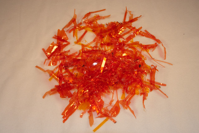
You’ll want to shred the gel(s) into small pieces in order to mix it up with the plastic beads.  I ran a few small sheets of orange & red gels through my paper shredder:

DSC_0008

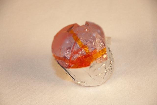
Make some forms out of aluminum foil in various shapes (you don’t want all your embers to be 100% identical).  I used things like batteries, a flashlight, and small cardboard boxes as forms, wrapping aluminum foil around them.  Then fill the form up with a mix of plastic beads and strips of the shredded gel.  Don’t overdo it with the gel, at least at first.  You probably want to experiment a bit to figure out the right mix:

DSC_0019

Fill up the form with more plastic beads, then place it in an oven at 400 degrees for approx. 20 minutes.  You should keep an eye on it to make sure the form doesn’t leak and the beads are melting.  If the beads aren’t fully melted after 20 minutes just leave them in the oven longer and consider turning up the heat slightly.  The gel strips have a much higher melting point (after all, they have to sit directly in front of 1000 watt stage lights for long periods of time) so don’t be surprised if they don’t melt like the beads to.  The color should still spread out throughout the mold as the beads melt.

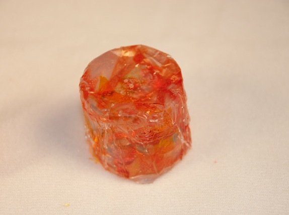
Once the beads have melted take the mold out of the oven and give it plenty of time to cool.  Remove the foil and you should end up with a translucent block of plastic:

DSC_0023

If you’re not happy with your first attempts then don’t fret.  You can always break up the plastic blocks using a hammer and then melt them down again in new forms.  Add more beads and/or pieces of gel to get them to look more like what you want.

The next important aspect of making a good fake fire is making a good flickering light effect.  If you’re doing this in a theater and you have a good quality DMX-based lighting system you might be able to program an effect to simulate this, but that’s a lot of work and can be a hassle if it has to be added to multiple cues.  After hunting around a bit I found a product called FauxFlame which is an electrical device you wire to an incandescent light to make it flicker randomly.  I bought a couple of these to add to my inventory of lighting toys and wired them into a couple electrical boxes so I can plug any light into them that I want.

The theater had an existing hearth with a few lights mounted inside it.  I installed a couple regular household incandescent bulbs wrapped in orange/yellow gels in the hearth, then put a dozen or so plastic embers on top, along with some fake fireplace logs that were bought from a local hardware store.  The lights were plugged into a FauxFlame and the result is quite impressive.  Here are a few photos and a link to a video showing the effect in action.  The set isn’t complete yet, so pardon the appearance of the fireplace.

IMG_0163

IMG_0158

IMG_0157

IMG_0156

And here’s a video of the fireplace in action: